Free models · Game-ready GLB
Kit
Every modern model below is a self-contained .glb under 25 MB that drops into three.js, Blender, Godot, Unity and Unreal, free to use and modify in commercial projects without attribution.
Load one straight from its CDN URL with a plain GLTFLoader, or take a whole themed set from the packs.
4,897 free GLB models
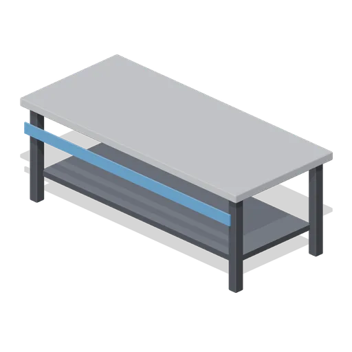
Display Table Long (Solar System and Astronauts)
A 2 m long display table with a grey top at 0.75 m, a lower shelf and a blue front stripe, for small sets and the orrery.
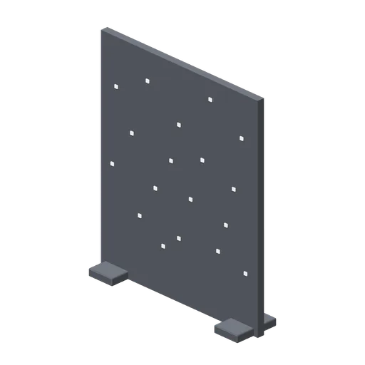
Star Backdrop Panel (Solar System and Astronauts)
A 2 m wide, 2.4 m tall dark backdrop panel scattered with proud glowing star dots, on two foot bases.
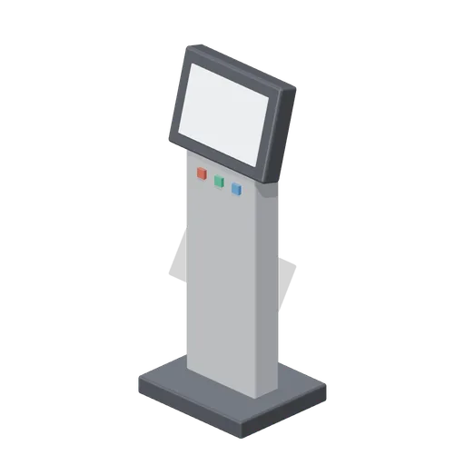
Info Kiosk (Solar System and Astronauts)
A 1.5 m gallery info kiosk with a blank lit screen tilted for reading, three coloured buttons and a dark base.
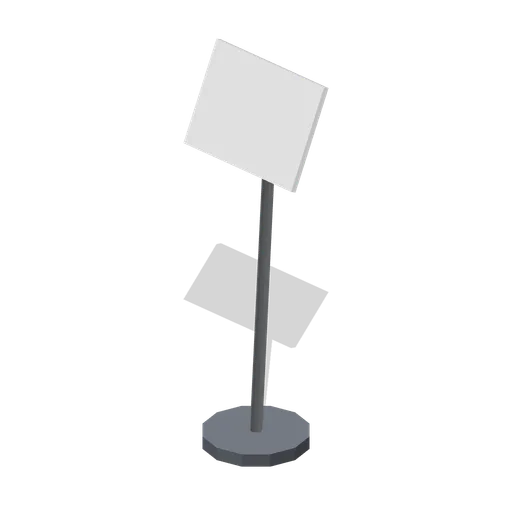
Label Stand Tall (Solar System and Astronauts)
A 1.15 m tall label stand with a blank plate, for freestanding interpretation panels away from the plinths.

Label Stand (Solar System and Astronauts)
A 0.9 m angled label stand with a blank white plate for a caption card, on a dark disc base.
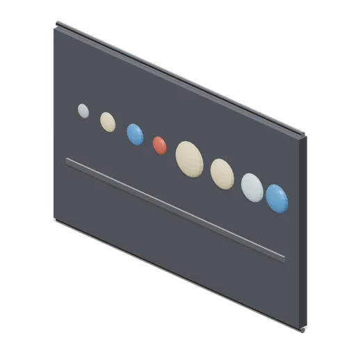
Planet Scale Chart Panel (Solar System and Astronauts)
A 1.8 m wall chart comparing planet sizes in ascending abstract discs on a baseline bar.
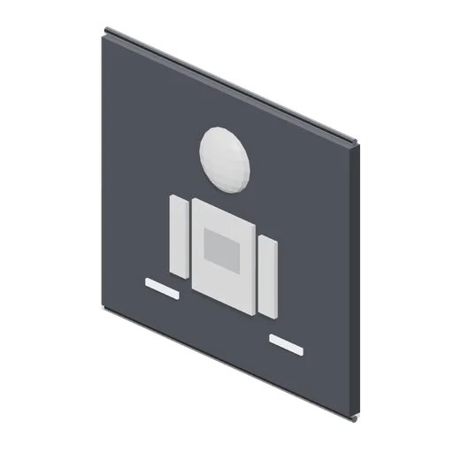
Astronaut Chart Panel (Solar System and Astronauts)
A 1.4 m wall chart of a spacesuit in abstract shapes: helmet disc, torso and limb bars with annotation blocks.
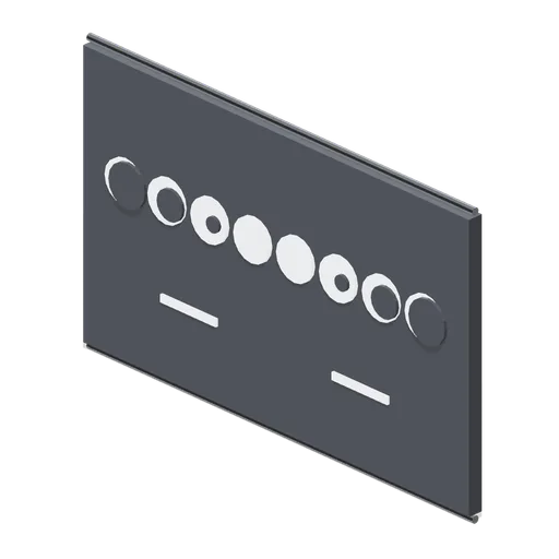
Moon Phases Chart Panel (Solar System and Astronauts)
A 1.8 m wall chart of the eight moon phases in abstract discs, from new to full, with annotation bars and no text.
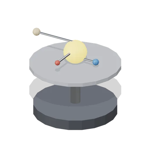 Animated
Orrery Stand (Solar System and Astronauts)
A 0.75 m mechanical orrery: a dark base with a steel column carrying a glowing sun and three orbiting planet arms that turn in loops.
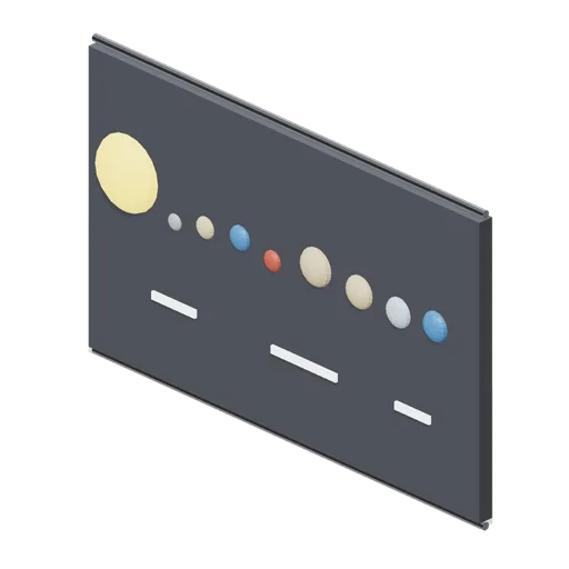
Solar System Chart Panel (Solar System and Astronauts)
A 1.8 m wall chart of the solar system in abstract shapes: a glowing sun disc and eight planet dots in a row with annotation bars.
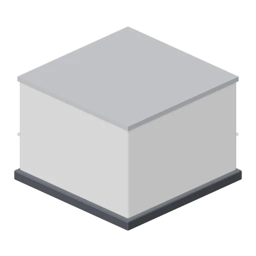
Display Plinth Wide (Solar System and Astronauts)
A 1.2 m wide, 0.9 m tall display plinth for the sun model and Saturn with its rings.
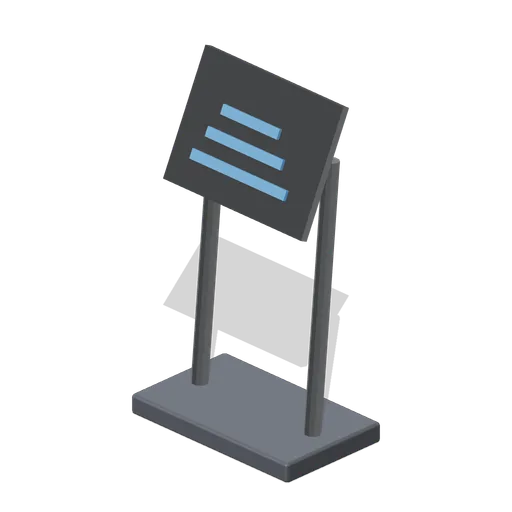
Mission Plaque (Solar System and Astronauts)
A 0.85 m angled mission plaque on two posts: a blank steel plate with three abstract bars and no readable text.
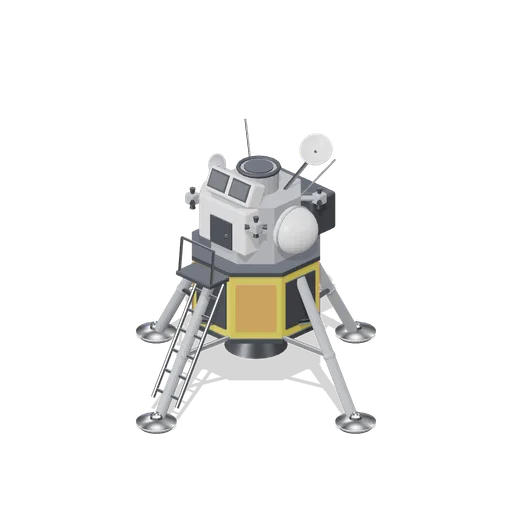
Lunar Lander (Solar System and Astronauts)
A 1.5 m four leg lunar lander: gold foil descent stage with its engine bell, braced legs on dished pads, a ladder and porch, and a grey ascent cabin with canted windows, hatch, tanks, thruster quads and dish antennas.
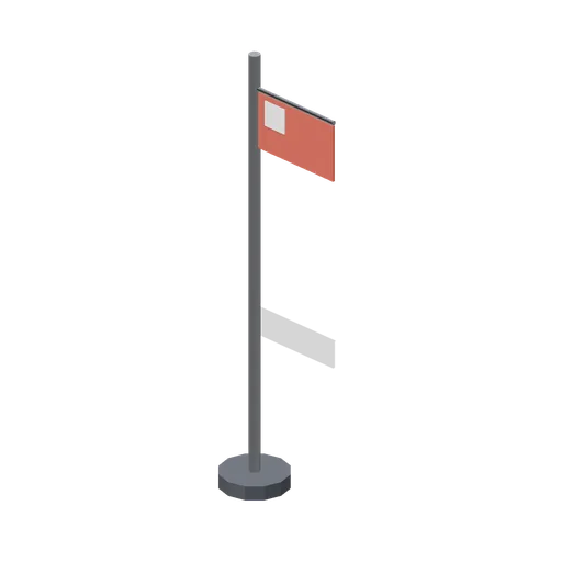
Moon Flag (Solar System and Astronauts)
A 1.6 m planted flag on a steel pole with a dark ground base: a blank red ensign with a white canton, carrying no markings.
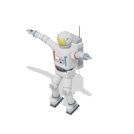
Astronaut Floating (Solar System and Astronauts)
A 2 m astronaut figure posed spread-eagled in a weightless drift, knees bent and toes down, with a free origin at the chest for placement in mid air.
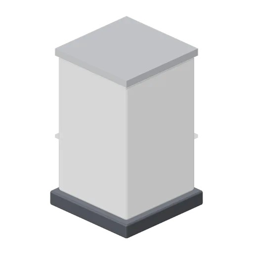
Display Plinth (Solar System and Astronauts)
A 0.9 m white display plinth on a dark base with a grey top plate, sized for one planet model.
 Animated
Comms Satellite (Solar System and Astronauts)
A 2 m wide communications satellite display model on a stand: gold foil bus with a ribbed radiator, twin hinged blue solar wings with a cell grid, a tracking dish on a gimbal that nods, thrusters and a whip antenna.
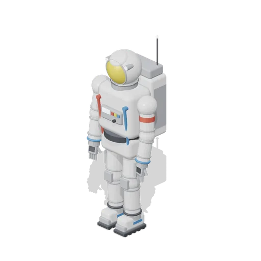
Astronaut Standing (Solar System and Astronauts)
A 2 m astronaut figure standing at ease: white suit with convolute joints, gold visor under a white hood, chest control box with hoses, life support backpack with antenna, treaded boots and a red commander stripe.
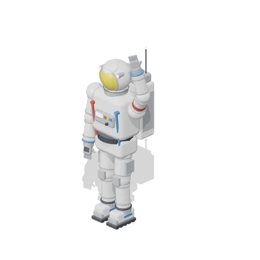 Animated
Astronaut Waving (Solar System and Astronauts)
A 2 m astronaut figure with its right arm raised in a wave on a named shoulder pivot, rocking gently in a looped clip. White suit, gold visor, chest box, backpack and treaded boots.

Comet Model with Long Tail (Solar System and Astronauts)
The comet model with longer ion and dust tails reaching 1.1 m, for a wall display where the tails can run clear of the shelf.
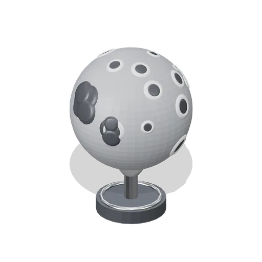
Earth Moon Model (Solar System and Astronauts)
A 0.28 m display model of Earth’s moon in cratered grey on a turned cradle, with dark maria plains and eighteen raised crater rims round sunk floors.
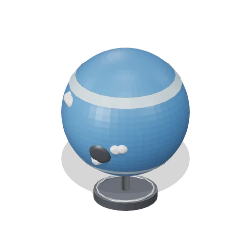
Neptune Planet Model (Solar System and Astronauts)
A 0.46 m display model of the planet Neptune in deep blue on a turned cradle, with raised ice bands, a dark storm spot and white cloud streaks.
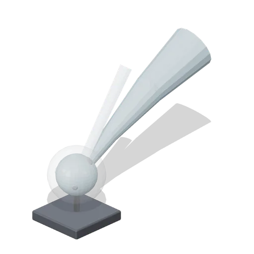
Comet Model (Solar System and Astronauts)
A 0.85 m display model of a comet: a patched ice head inside a glass coma on a steel stem, with a glowing straight ion tail and a curved dust tail streaming up behind it.
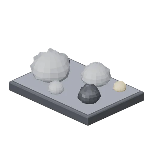
Asteroid Set on Tray (Solar System and Astronauts)
Six jagged asteroids from 0.07 to 0.24 m across in grey, dark and sand rock, presented on a dark display tray with a steel inlay.